- 您现在的位置:买卖IC网 > Sheet目录1991 > CS4339-KSZR (Cirrus Logic Inc)IC DAC STER 24BIT 96KHZ 8-SOIC
10
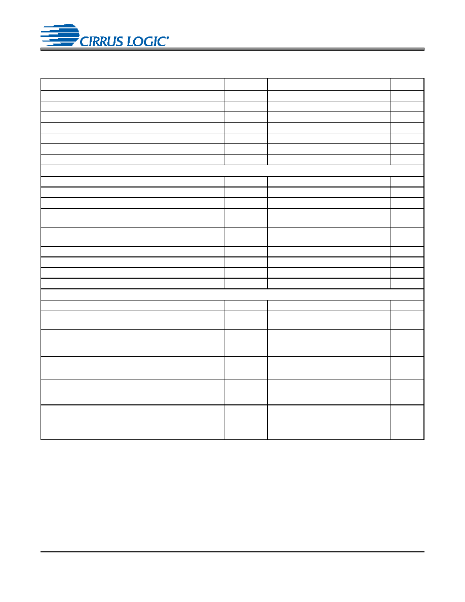
CS4334/5/8/9
SWITCHING CHARACTERISTICS
Notes:
9.
In Internal SCLK Mode, the Duty Cycle must be 50%
1/2 MCLK Period.
10. The SCLK / LRCK ratio may be either 32, 48, or 64. This ratio depends on part type and MCLK/LRCK
ratio. (See figures Figures 10-13)
Parameters
Symbol
Min
Typ
Max
Units
Input Sample Rate
Fs
2
-
100
kHz
MCLK Pulse Width High
MCLK/LRCK = 512
10
-
1000
ns
MCLK Pulse Width Low
MCLK/LRCK = 512
10
-
1000
ns
MCLK Pulse Width High
MCLK / LRCK = 384 or 192
21
-
1000
ns
MCLK Pulse Width Low
MCLK / LRCK = 384 or 192
21
-
1000
ns
MCLK Pulse Width High
MCLK / LRCK = 256 or 128
31
-
1000
ns
MCLK Pulse Width Low
MCLK / LRCK = 256 or 128
31
-
1000
ns
External SCLK Mode
LRCK Duty Cycle (External SCLK only)
40
50
60
%
SCLK Pulse Width Low
tsclkl
20
-
ns
SCLK Pulse Width High
tsclkh
20
-
ns
SCLK Period
Base-Rate Mode
MCLK / LRCK = 512, 256 or 384
tsclkw
--
ns
SCLK Period
High-Rate Mode
MCLK / LRCK = 128 or 192
tsclkw
--
ns
SCLK rising to LRCK edge delay
tslrd
20
-
ns
SCLK rising to LRCK edge setup time
tslrs
20
-
ns
SDATA valid to SCLK rising setup time
tsdlrs
20
-
ns
SCLK rising to SDATA hold time
tsdh
20
-
ns
Internal SCLK Mode
LRCK Duty Cycle (Internal SCLK only)
-50
-
%
SCLK Period
tsclkw
--
ns
SCLK rising to LRCK edge
tsclkr
--
s
SDATA valid to SCLK rising setup time
tsdlrs
--
ns
SCLK rising to SDATA hold time
MCLK / LRCK = 512, 256 or 128
tsdh
--
ns
SCLK rising to SDATA hold time
MCLK / LRCK = 384 or 192
tsdh
--
ns
1
128
Fs
----------------------
1
64
Fs
-------------------
1
SCLK
-----------------
tsclkw
2
------------------
1
512
Fs
----------------------10
+
1
512
Fs
----------------------15
+
1
384
Fs
----------------------15
+
发布紧急采购,3分钟左右您将得到回复。
相关PDF资料
CS4340-CZZ
IC DAC 24BIT 96KHZ 101DB 16TSSOP
CS4341-CZZ
IC DAC STER 24BIT 96KHZ 16TSSOP
CS4341A-KSZ
IC DAC STER 24BIT 192KHZ 16SOIC
CS4351-DZZ
IC DAC STER 112DB 192KHZ 20TSSOP
CS4352-DZZ
IC DAC STER 102DB 192KHZ 20TSSOP
CS4354-CSZ
IC DAC 24BIT SRL 14SOIC
CS4360-KZZ
IC DAC STER 6CH 102DB 28TSSOP
CS4361-CZZR
IC DAC STER 6CH 105DB 20-TSSOP
相关代理商/技术参数
CS4-34
制造商:SUPERWORLD 制造商全称:Superworld Electronics 功能描述:POWER TRANSFORMER
CS4340
制造商:CIRRUS 制造商全称:Cirrus Logic 功能描述:24-Bit, 96 kHz Stereo DAC for Audio
CS4340_05
制造商:CIRRUS 制造商全称:Cirrus Logic 功能描述:24-Bit, 96 kHz Stereo DAC for Audio
CS4340A
制造商:CIRRUS 制造商全称:Cirrus Logic 功能描述:24-Bit, 192 kHz Stereo DAC for Audio
CS4340A_05
制造商:CIRRUS 制造商全称:Cirrus Logic 功能描述:24-Bit, 192 kHz Stereo DAC for Audio
CS4340A-KS
制造商:Rochester Electronics LLC 功能描述: 制造商:Cirrus Logic 功能描述:
CS4340A-KSR
制造商:Rochester Electronics LLC 功能描述: 制造商:Cirrus Logic 功能描述:
CS4340A-KSZ
功能描述:数模转换器- DAC IC 24-Bit 192kHz Stereo DAC for Audio RoHS:否 制造商:Texas Instruments 转换器数量:1 DAC 输出端数量:1 转换速率:2 MSPs 分辨率:16 bit 接口类型:QSPI, SPI, Serial (3-Wire, Microwire) 稳定时间:1 us 最大工作温度:+ 85 C 安装风格:SMD/SMT 封装 / 箱体:SOIC-14 封装:Tube